Splice Kit Guide
All Systems
Troubleshooting Inaccurate Meter Reads
Splice Kit Guide
The process of connecting meters with the splice kits is very easy. What you will be doing is taking the wires and making sure to line up like colored cables for pulse wires. Some systems vary color types so make sure you are connecting the correct wires together. There usually a guide on the side of the transceiver itself if encoded, pulse wires or (2 wire) meters aren’t polarity specific (unless dealing with electric meters) but it's best to pair like types:
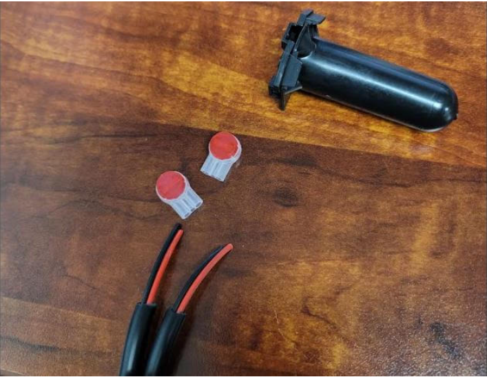
Example A: Splice kit with watertight grease cap
Keeping the shielding intact, place 1 set of wires into the snaplock connector (Making sure the wires go all the way to the end of the connector):
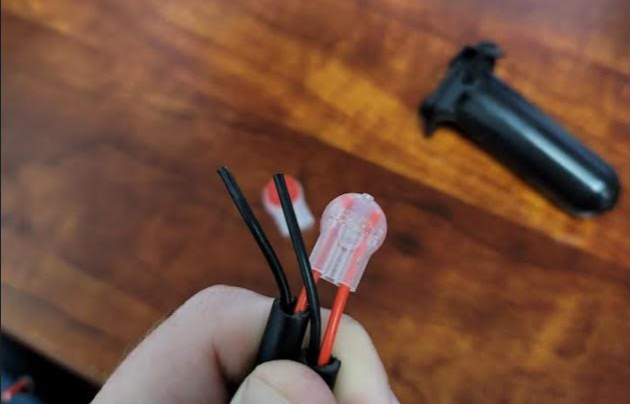
Example B: Insert wires to the end of the cap as far back as possible.
Using channel locks or some sort of wrench, line up the wrench to cover the red button on the top and squeeze until you see and feel the kit lock onto the wire. The red button should now be flush with the white part of the connector:
Fig. C: Clamp down on the red cap keeping wires in as deep as possible.
Fig. D: After snapping down wires, turn over and verify wires are tight and don't slide out.
Do the same for the other set of wires.
Example E: After snapping down the second set of wires.
When both sets are complete, place the connectors into the tube filled with grease all the way to the bottom to weatherproof the wires.
Fig. F: Insert wires into the grease cap as far as you can get them before closing to prevent water getting in.
IMPORTANT: You do NOT strip the wire bare before putting them in the connector pieces as they use the shielding on the wire to help keep them secure on the wire itself. Make sure that the wire is placed in the connector as far as you can place it to make sure it gets a solid connection on the wire and cannot be pulled free.
Related Articles
How to Use a Multimeter to Check if a Water Meter is Providing Pulses (Using the Continuity Setting)
Introduction Using a multimeter to check if your water meter is providing pulses is a straightforward process. This guide will walk you through the steps to check the pulses using the continuity setting on your multimeter. Tools Required Digital ...